1.Applicant and Feature
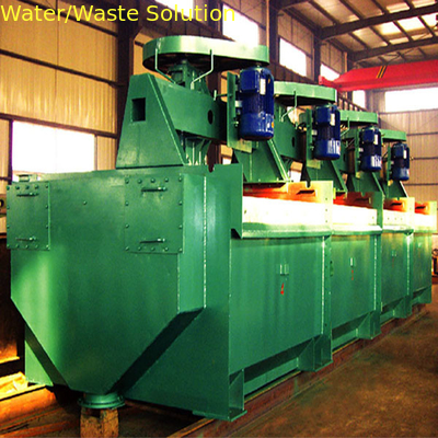
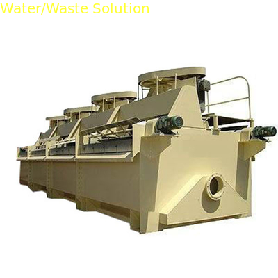
(1) The machine is deep groove type inflatable mechanical stirring flotation machine. Its design is divided into two types: XCF type with slurry suction ability, KYF type without slurry suction ability.
If the two models operate in combination way, namely , the first groove of each operation group must be equipped with XCF type and the remaining slots are equipped with KYF type flotation machine. the working groups are arranged horizontally. It is no need foam pump to return the foam.
If only open KYF flotation machine ,all working groups will be set as Ladder configuration with a foam pump for returning back the bubble .
The machine is suitable for rough sweep and selected operations of large and medium-sized concentrator. It is optional for non-ferrous metals, ferrous metals and non-metallic minerals selection with incoming material size range tail 0.3-0.01mm (-0.074 grain content of more than 50%).
(2) Due to the use of a single-walled inverted blade double inverted cone-shaped impeller, porous cylinder gas distributor, suspended stator and advanced air volume and liquid Surface automatic control technology, Our flotation machine has such characteristic as simple structure, easy maintenance, light wear, smooth and reliable operation, strong air dispersion ability, good solid suspension, low energy consumption, stable liquid level and high sorting efficient.

2. Structure and Working Principle
(1) Structure
KYF type flotation machine structure shown in attached drawing, the impeller mechanism is composed of impeller (1), hollow spindle (5), air distributor (2) and bearing body (6) and so on. XCF type flotation machine structure shown in Figure 2, compared with the KYF type, only the replacement of the impeller (1), increased the takeover (8), the central tube (9), cover (11) ) And to the mine.
The impeller mechanism is mounted on the tank beam and is driven by the motor through the V-belt.
KYF-type impeller section was double inverted cone-shaped, there are 8 back to the blade, XCF-type impeller increased on the blade, the air distributor tail cylindrical, surrounded by small holes, placed in the impeller center: stator four components, Each with 4-8 radial blades, placed on the oblique side of the impeller, fixed with a bracket on the bottom of the tank.
(2) Working Principle
When the impeller of the KYF flotation machine is rotating, the surrounding slurry in the tank is sucked into the impeller blades through bottom slot impeller. Its upper impeller leaves can also be sucked and abstracted feeding ore and middle ore. while the pulp is inhaled, the low pressure air offered by the blower air distributor of the impeller chamber via its hollow shaft , and then enter the impeller pieces through small holes around the distributor. The fully mixed pulp with air will be discharged out from the periphery of the upper half of the impeller, and the discharged pulp direction is inclined upward, and the stable flow is charged and positioned by the stator installed at the top of the impeller, then finally enter into the main slurry tank.
3.Technique Parameter (View Table below )
| Model |
Effective Volume
m3
|
Slot Dimension LXWXH |
Capacity
m/min
|
Main Shaft motor KW |
Impeller DN
mm
|
Impeller speed
m/s
|
Max. inflatable volume
m3/m2/min
|
wind pressure
kpa
|
| XCF-1 |
1 |
1000X1000X1100 |
0.2-0.6 |
4/5.5 |
400 |
7.0 |
2 |
>14 |
| KYF-1 |
0.2-1 |
3/4 |
340 |
5.0 |
| XCF-2 |
2 |
1300X1300X1250 |
0.4-1.2 |
5.5/7.5 |
470 |
7.0 |
2 |
>16 |
| KYF-2 |
0.4-2 |
4/5.5 |
410 |
5.3 |
| XCF-3 |
3 |
1600X1600X1400 |
0.6-1.8 |
7.5/11 |
540 |
7.0 |
2 |
>18 |
| KYF-3 |
0.6-3 |
5.5/7.5 |
480 |
5.5 |
| XCF-4 |
4 |
1800X1800X1500 |
1.2-2.5 |
11/15 |
620 |
7.2 |
2 |
>19.8 |
| KYF-4 |
1.2-4 |
7.5/11 |
550 |
5.76 |
| XCF-8 |
8 |
2200X2200X1950 |
3-5 |
18.5/22 |
720 |
7.3 |
2 |
>21.5 |
| KYF-8 |
3-8 |
11/15 |
630 |
5.77 |
| XCF-16 |
16 |
2800X2800X2400 |
4-10 |
30/37 |
860 |
7.5 |
2 |
>22.5 |
| KYF-16 |
4-16 |
22/30 |
740 |
6.2 |
| XCF-24 |
24 |
3100X3100X2700 |
6-12 |
55 |
920 |
7.5 |
2 |
>28 |
| KYF-24 |
6-24 |
37 |
800 |
6.84 |
| XCF-38 |
38 |
3600X3600X3400 |
10-20 |
55 |
1050 |
7.8 |
2 |
>32 |
| KYF-38 |
10-38 |
45 |
880 |
6.36 |
| XCF-40 |
40 |
3800X3800X3400 |
10-40 |
75 |
1050 |
7.5 |
2 |
>32 |
| KYF-40 |
10-40 |
55 |
880 |
6.9 |
| XCF-50 |
50 |
4200X4200X3500 |
10-25 |
90 |
1200 |
8.42 |
2 |
>33 |
| KYF-50 |
10-50 |
75 |
1030 |
7.07 |
4.Equipment installation and commissioning
(1). The spindle components assembled in the factory. Before assembly , checking if all parts with design requirement, if the spindle is bent and carrying on static balance test for large pulley and impeller as per drawings technical requirements .
(2) Do around 4 hours unload inspection after the impeller is installed well. The rotation of the flotation machine is clockwise direction, check if the bearing is hot and the air temperature rise shall not be greater than 50℃, and check if the mechanical operation is smooth without abnormalities.
(3) Make sure each first slot installed XCF, the remaining slot installed KYF in the field assembly.
(4) The slots installation must be solid with overflow weir in same level as the beam in site installation.
(5) After installation, the spindle components will be hoisted to the main body of the tank to ensure the spindle and the beam are on vertical surface with acceptable vertical tolerance as 0.1: 100.
(6) The adjustable gap range between impeller circle and the stator is from 20mm to 95mm.
(7) .Assure the scraper and the shaft in horizontal concentric, flexible operation.
(8) The gate between middle tank and tailing tank must be flexible.
(9) Scraper bearings should add ZG-2 grease.
(10) According to the process configuration requirements, Every group or unit can be composed of 2-6 slots, all slot connection with a 5mm thick pad are all by bolt. And the pad can be adhesive bonding to the tank wall in advance with 401 glue, all interface point should have no slurry leakage. After negotiation, it can be carried on site welding joint.
(11) After all the installation of the unit, do unload rotation , after test in normal, filling water full in the tank and then continuously run for 8 hours, if no problem as qualified to be put into production application.
5. Basic conditions
Adopt same flow direction two concrete beams
6. Equipment operation
(1) First start the blower for air supply, and then open the flotation machine sequentially from the last process slot to the front one to get rid of overload or press tank.
(2) Can stop the machine when all ore feeding completely stopped, and the stop sequence is stop from the first to the last back lot , after that the blower can be stopped with no need draining ore slurry, it’s better to have full slot slurry for facilitate next time start using.
(3) Confirm appropriate ore surface height as per selection requirement
This height can be controlled by level control system or electric discharge
(4) inflatable volume can be adjusted by intake valve based on different ore properties and different sorting requirements.
(5) During operation, pay attention to check the temperature of motor and bearing, Inject lube oil to all lubrication points regularly to follow normal equipment operation and maintenance under civilized production.
7. Equipment Maintenance
(1) Tighten the loose bolts and adjust the tension of the V-belt at any time.
(2) Regularly clean or maintain main bearing or replace the wear parts.
(3) Repair and dis-assembly of the spindle parts:
Loosen the A-type butterfly valve connecting bolts and the connecting rods of the bearing body and the beam assembly, lift the spindle parts through the top of the spindle and mount them vertically on the maintenance work rack, and then remove the large pulley and On the bearing gland and the lower part of the spindle impeller, flange and other pieces, hanging up the spindle, washable or install the moving parts, clean, first installed on the oil ring, and the upper bearing gland mounted on the spindle, Pay attention to the lubrication of calcium grease ZG-2, then the spindle hanging into the bearing body and in turn installed the lower parts, and finally installed a large pulley, hand-rotating large pulley, while adjusting the bearing gland and bearing body clearance to ensure that Spindle can be free to turn for the degree, such as no maintenance work frame, but also in the flotation after the float on the tank body.
8. Lubricants, Grease grades
(1) Gear box lubricants: Adopt # N32 and N46 in summer and winter respectively
(2) Motor lubrication: Adopts ZL-3 grease.
(3) Blower lubrication: Use 10-20MS oil.
(4) Other parts of the lubrication: Use ZG-2 grease.
9. Blower selection and flotation machine order
(1) Blower selection
the size of the blower wind pressure depends on the size of the flotation machine, air volume to determine the type of flotation machine inflatable capacity can be adjusted between 0.1-1.7m3 / m2 / min, non-ferrous metal mines generally 1-1.5m3 / M2 / min, phosphate and hematite generally change between 0.1-0.5m3 / m2 / min, the amount of inflation according to the nature of the mine ore and sorting method to determine the amount of gas to determine the determination and then according to the flotation Machine total surface area to determine the total air volume, the use of this air volume plus a little coefficient to determine the air volume capacity. At present, China can be equipped with the type of flotation machine fan fan machine produced by the machine for the flotation machine D-type fan, for example, and XCF-16 and KYF-16 supporting fans are: D85-21, D100-21 , D120-21, D150-21, D250-21, D300-21, D400-21.
(2) Flotation machine order
Before production , the user or buyer shall provide the manufacturer process configuration diagram to determine the flotation machine, ore feeding tank, intermediate tank, tailing tank, number of scraper transmission device and some structure change related to ore selection.
10. Wear Part Table ( Each Flotation Machine demand Volume )
| SN |
Item |
Single Unit Qty |
Remark |
| 1 |
Suction tank stator |
1 |
|
| 2 |
Suction chute impeller |
1 |
|
| 3 |
DC slot stator |
1 |
|
| 4 |
DC chute impeller |
1 |
|
11.Contact us
Bruce Xiong / Peter Lee
Owner/Marketing Director
Loren Industry Co., Ltd
Water Care and Energy Expert for 16 years
What app /WeChat/ mobile: +86-13921106199 or 13952466865
Skype: Ginkeneer or peterlee4778
Mail: lorenindustry@163.com or Lorenindustry@126.com
web: www.lorenindustry.com or www.lorenenvirotech.com
One Time Trust , Long Lasting Rewarding
 Your message must be between 20-3,000 characters!